

Step 8: The Digital Thread – Requirement Traceability (Satisfaction)
In Step 2, you defined the “Legal Rules” of the system (Requirements). In Steps 4, 5, 6 and 7, you built the “Physical Reality” (Structure) and the “Operational Logic” (Behavior). Now, we come to the most critical part of Model-Based Systems Engineering (MBSE): The Digital Thread.
Requirement Traceability is the act of proving that your design actually fulfills the requirements you set at the beginning. In traditional engineering, this is often a manual spreadsheet task. In SysML v2, this is not just a line on a diagram; it is a formal Assertion that the design is valid according to the rules.
1. The satisfy Keyword
To link a design element to a requirement, SysML v2 provides the satisfy keyword. A Satisfy Requirement Usage is a specialized kind of assertion. It essentially tells the modeling tool: “I am asserting that this specific part meets the criteria of this specific requirement.”
This creates a bidirectional link: you can trace from the requirement down to the hardware that implements it, and from the hardware up to the requirement it satisfies.
2. The Satisfying Feature (by)
When you satisfy a requirement, you must identify what is doing the satisfying. This is called the Satisfying Feature. We use the keyword by to point to the specific hardware, behavior, or assembly responsible for the rule.
- Syntax:
satisfy <RequirementDefinition> by <DesignElementUsage>;
For example, if we have a rule about temperature limits, we satisfy that rule by our specific smart home assembly (home_01). This tells the tool that home_01 is the entity being tested against that rule.
3. Closing the Verification Loop
Why do we go through the trouble of formally linking these elements?
- Automated Verification: Modeling tools can use these links to generate “Success/Failure” reports. If the
currentTempin your model simulation exceeds the limit set in your requirement, the tool can flag thesatisfylink as “Failed,” alerting you to a design flaw. - Impact Analysis: If a requirement changes later (e.g., the max temperature drops to 24°C), you can instantly see which parts of your physical system are affected because they are digitally tied together. You don’t have to guess; the model tells you.
- Compliance: For safety-critical systems, you often need to prove to regulators that every requirement has been addressed. The
satisfyrelationship provides this evidence directly from the model.
Hands-On: Creating ClimateTraceability.sysml
We will create a final “Bridge” package. This package will import the Requirements from Step 2 and the System Assembly from Step 4, then formally link them together. This file acts as the “Verification Report” for your project.
- Create the New File
Navigate to your project folder Smart Home Climate System in the Navigator pane. Click on New File.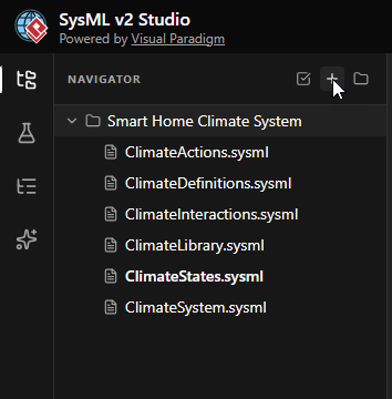
- Name the File
EnterClimateTraceability.sysmlas the filename and click Create.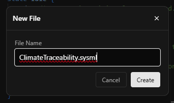
- Define the Package and Imports
Start by defining the package. To create the link, this file needs to “see” both the requirement definition and the system instance. Therefore, we import bothClimateDefinitions(where the Requirement lives) andClimateSystem(where thehome_01instance lives).package ClimateTraceability { // Import everything to bring the 'Rule' and the 'Design' into one space. private import ClimateLibrary::*; private import ClimateDefinitions::*; private import ClimateSystem::*; }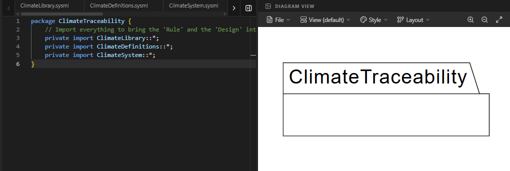
- Create the Satisfaction Link
Now, we write the assertion. We use thesatisfyrequirementkeyword followed by the requirement name, and thebykeyword followed by the part usage name.// Assert that our specific house (home_01) fulfills the // temperature limit we defined in Step 2. satisfy requirement TemperatureRequirement by home_01;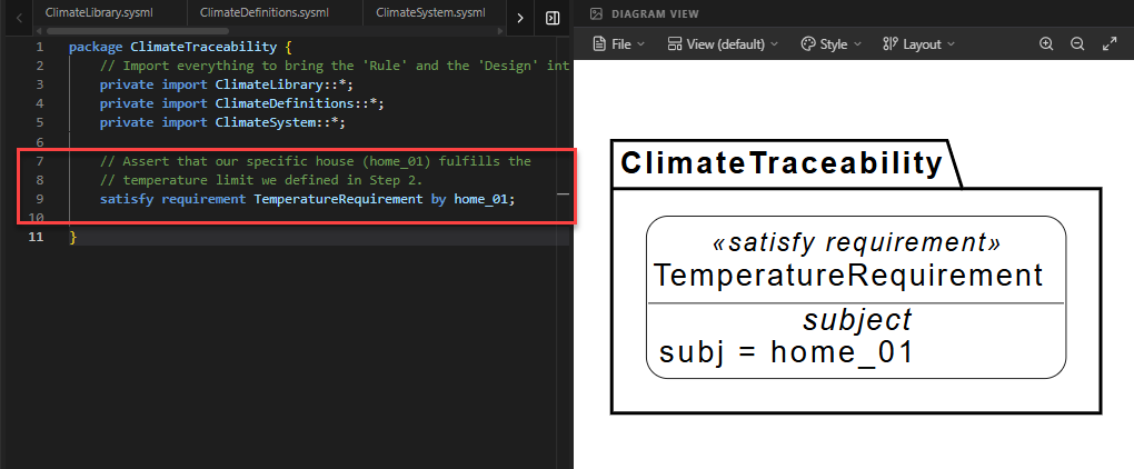
Code Explanation: This single line creates a formal traceability link in the model database. It states: “The instance
home_01is responsible for satisfying theTemperatureRequirement.” - Add Documentation
Finally, add a documentation block to explain the purpose of this link for future reviewers.doc /* * This satisfaction link proves that the 'home_01' assembly, * which includes a thermometer and controller, is the * entity responsible for maintaining the temperature * requirement of < 298.15 K. */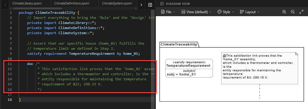
Full Code for Step 8
package ClimateTraceability {
// 1. MODULAR IMPORTS
// We import everything to bring the 'Rule' and the 'Design' into one space.
private import ClimateLibrary::*;
private import ClimateDefinitions::*;
private import ClimateSystem::*;
// 2. REQUIREMENT SATISFACTION (The Digital Thread)
// We assert that our specific house (home_01) fulfills the
// temperature limit we defined in Step 2.
// This creates a formal traceability link in the model database.
satisfy requirement : TemperatureRequirement by home_01;
// 3. DOCUMENTATION OF PROOF
    doc /*
         * This satisfaction link proves that the 'home_01' assembly,
         * which includes a thermometer and controller, is the
         * entity responsible for maintaining the temperature
         * requirement of < 298.15 K.
         */
}Summary of SysML Elements Used
The table below summarizes the key SysML v2 elements introduced in this final step.
| SysML Element | Purpose | Code Context |
|---|---|---|
satisfy |
Creates a formal assertion that a design element fulfills a requirement. | satisfy requirement TemperatureRequirement ... |
by |
Identifies the specific design feature (part or behavior) that satisfies the requirement. | ... by home_01; |
Conclusion: Congratulations on Completing Your First SysML v2 Model!
You have successfully journeyed through the core pillars of Model-Based Systems Engineering using SysML v2. Let’s look back at what you have built:
- Step 1 & 2 (The Mission): You defined the Requirements and Use Cases, establishing the rules and goals of your system.
- Step 3 (The Blueprints): You created Part Definitions and Ports, defining the modular components like Sensors and Controllers.
- Step 4 (The Assembly): You built the Internal Block View, instantiating those components into a real system (
home_01) and wiring them together. - Step 5, 6 & 7 (The Behavior): You defined the Action Flow, Sequence Flow and State Machine, giving your system a “brain” that can react to changes and perform logic.
- Step 8 (The Proof): You closed the loop with Requirement Traceability, formally proving that your design satisfies your initial rules.
By following this tutorial, you have moved beyond simple diagrams to create a digital twin—a rigorous, interconnected, and verifiable model of a Smart Home Climate System. You have learned how SysML v2 uses textual syntax to create a powerful “Digital Thread” that connects every aspect of engineering, from abstract goals to concrete hardware.
Thank you for reading and coding along! We hope this tutorial has demystified SysML v2 and inspired you to explore more complex systems. Happy Modeling!
Ready to Model Your Own Systems?
Stop drawing static diagrams. Start building intelligent, verifiable models with SysML v2 Studio. Experience the power of the Digital Thread today.
