

Step 5: Defining Behavior – The Action View (Action Definitions and Successions)
In Step 4, we built the “Skeleton” of our system—the parts, their attributes, and their connections. Now, we need to define the “Brain”—the Behavior. In SysML v2, behavior is primarily modeled using Actions.
The Action View (often rendered as an Activity or Action Flow Diagram) shows how the system performs work over time. It defines the sequence of steps, how data flows through a process, and the logic that drives decision-making.
1. Action Definition vs. Usage
Following our consistent “Cookie Cutter” pattern, we distinguish between the blueprint for a process and an instance of that process.
- Action Definition (
action def): A reusable blueprint for a behavior. For example, “Regulate Temperature” is a definition that describes the general logic any controller might use. - Action Usage (
action): A specific performance of that behavior within a larger context. When a specific controller executes the logic, it is performing an instance of that action.
2. Parameters: The Data Flow
Actions are not isolated; they need information to work and must produce results. We use Parameters to define these data interfaces:
in: Input data required to start the action (e.g., the current temperature reading).out: Output data produced when the action finishes (e.g., a command to turn the heater on or off).
These parameters allow actions to be chained together, where the out of one step becomes the in of the next.
3. Succession: The Order of Events
In SysML v2, we don’t just “draw lines” between steps arbitrarily. We use a Succession relationship to strictly assert that one event happens after another. This creates a clear timeline of execution.
SysML v2 introduces a powerful shorthand for successions:
first: Identifies the starting point of a sequence.then: A keyword that says: “Wait for the previous step to finish completely, then start this next step.”
Every action automatically inherits two special implicit nodes: start (the trigger) and done (the completion). By linking these, we define the full lifecycle of the behavior.
4. Performing Actions: Linking Behavior to Structure
Defining an action is only half the battle. We must also specify who performs it. In SysML v2, we use the perform keyword to bind an action to a specific part (like our Controller). This links the structural view (Step 4) with the behavioral view (Step 5), creating a complete system model.
Hands-On: Creating ClimateActions.sysml
We will create a new file to define the control logic. This logic will describe how our system reads a sensor, processes the data, and decides whether to act. Because this is a new file, we will practice modular imports again.
- Create the New File
Navigate to your project folder Smart Home Climate System in the Navigator pane. Click on New File.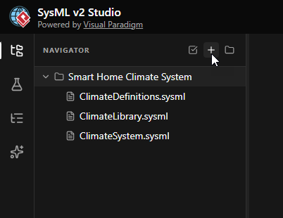
- Name the File
EnterClimateActions.sysmlas the filename and click Create.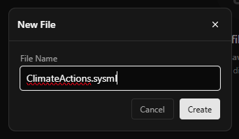
- Define the Package and Imports
Start by defining the package and importing the necessary libraries. We needClimateLibraryfor data types andClimateDefinitionsto reference our existing Parts.package ClimateActions { private import ClimateLibrary::*; private import ClimateDefinitions::*; }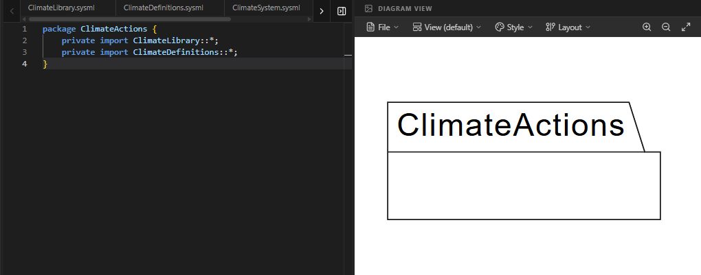
- Define the Action Blueprint (
RegulateTemperature)
Inside the package, we define the high-level behavior. We declare two input parameters:currentTempandsetPoint. These represent the data the action needs to operate.action def RegulateTemperature { // Parameters for the overall process in currentTemp : ThermodynamicTemperatureValue; in setPoint : ThermodynamicTemperatureValue; // Internal steps will go here }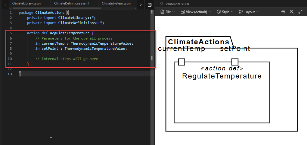
- Add Internal Action Steps
Now we break the behavior down into smaller steps. Inside the action definition, we define two sub-actions:compareTemps: Takes the inputs and calculates the difference.determineCommand: Takes that difference and decides if heating is needed.
Note how we map the parameters:
in temp = currentTempmeans the sub-action’s input ‘temp’ is fed by the parent action’s ‘currentTemp’.// Step A: Compare the temperatures action compareTemps { in temp = currentTemp; in target = setPoint; out diff : Real; } // Step B: Decide if the heater is needed action determineCommand { in tempDiff = compareTemps.diff; out status : Boolean; }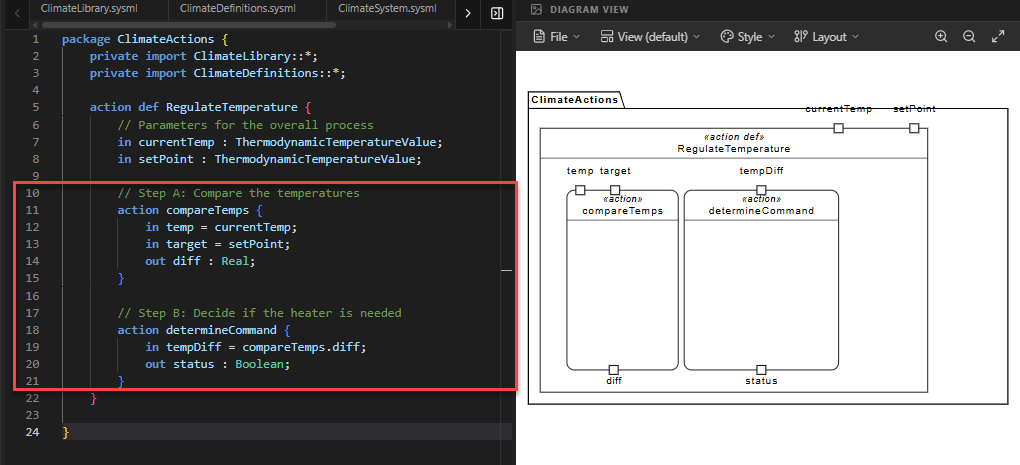
- Define the Sequence (Succession)
We use thefirstandthenkeywords to choreograph the order of operations. This ensures the system doesn’t try to make a decision before it has compared the temperatures.// Choreography: Define the timeline first start; then action compareTemps; then action determineCommand; then done;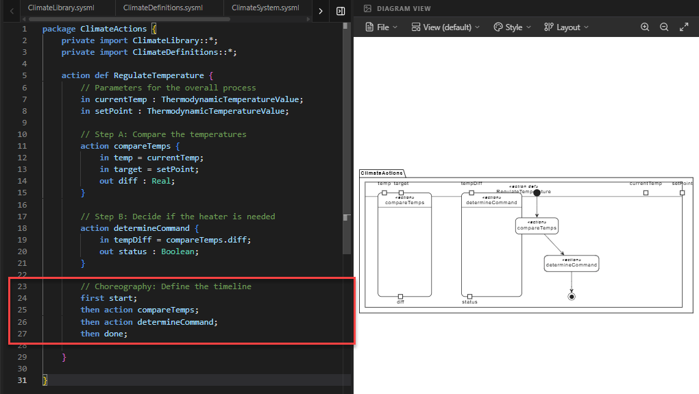
Code Explanation: This sequence asserts: Start → Compare → Decide → Done. It creates a strict causal chain.
- Link Behavior to Structure (
SmartController)
Finally, we need to assign this behavior to a part. We create a new part definitionSmartControllerthat specializes (inherits from) our originalController. We use theperformkeyword to state that this controller is responsible for executing theRegulateTemperatureaction.part def SmartController :> Controller { // 'perform' tells the tool that this part is the one // responsible for carrying out the action. perform action regulate : RegulateTemperature; }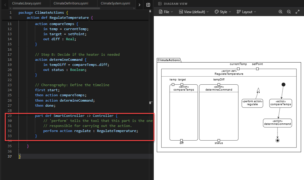
Code Explanation: The symbol
:>indicates specialization.SmartControlleris a specific type ofControllerthat has the added capability of performing the regulation logic.
Full Code for Step 5
package ClimateActions {
// 1. MODULAR IMPORTS
private import ClimateLibrary::*;
private import ClimateDefinitions::*;
// 2. ACTION DEFINITION (The behavioral blueprint)
action def RegulateTemperature {
// Parameters for the overall process
in currentTemp : ThermodynamicTemperatureValue;
in setPoint : ThermodynamicTemperatureValue;
// 3. INTERNAL ACTION USAGES (The steps)
        // Step A: Compare the temperatures
        action compareTemps {
            in temp = currentTemp;
            in target = setPoint;
            out diff : Real;
        }

        // Step B: Decide if the heater is needed
        action determineCommand {
            in tempDiff = compareTemps.diff;
            out status : Boolean;
        }
// 4. CHOREOGRAPHY (Succession shorthand)
// We use 'first/then' to define the timeline of these events.
first start;
then action compareTemps;
then action determineCommand;
then done;
}
// 5. PERFORMING THE ACTION (Binding to a part)
// We add this to our Controller blueprint from Step 3
    part def SmartController :> Controller {
        // 'perform' tells the tool that this part is the one
        // responsible for carrying out the action.
        perform action regulate : RegulateTemperature;
    }
}
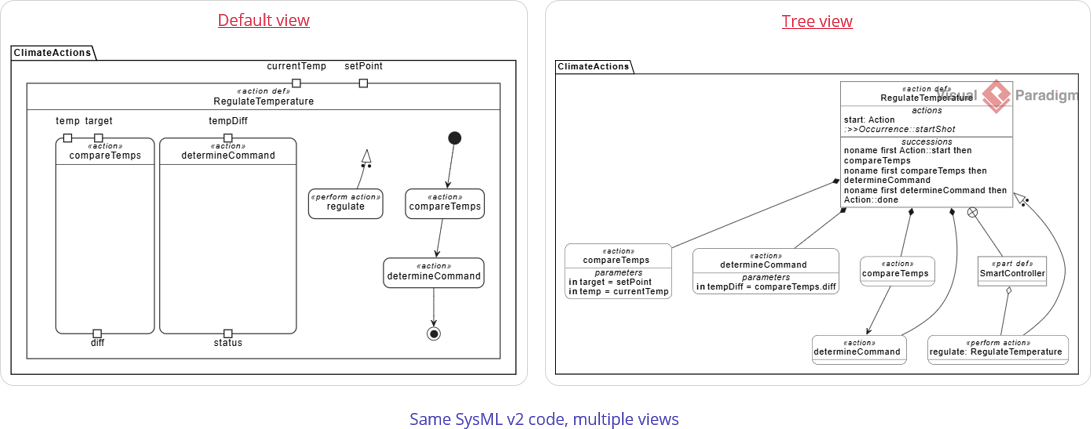
Extended Reading: Switching Diagram Views
A single namespace in SysML v2 can contain multiple aspects of a system—structure, behavior, requirements, and more. By default, the SysML v2 Studio attempts to intelligently analyze your code and render the most appropriate diagram type (for example, showing an Action Flow for behavior or a Block Definition for structure).
However, you may want to view your model from a different perspective. For instance, while this step focuses on the Action View, you might want to verify the hierarchical structure of your actions using a Tree View.
How to Switch Views:
- Locate the View dropdown menu at the top of the Diagram Viewer panel. It usually displays the current view name (e.g., “Default”).
- Click the dropdown and select Tree.
The diagram will immediately update to show a hierarchical tree structure of your elements. This is particularly useful for understanding the containment relationships within complex action definitions or part structures.
Summary of SysML Elements Used
The table below summarizes the key SysML v2 elements introduced in this step, their purpose, and how they appear in the code.
| SysML Element | Purpose | Code Context |
|---|---|---|
action def |
Defines a reusable blueprint for a behavior or process. | action def RegulateTemperature { ... } |
in / out Parameters |
Defines the data interface of an action (inputs and outputs). | in currentTemp : ... and out diff : Real. |
action [name] |
Defines a sub-step (usage) within a larger action. | action compareTemps { ... } inside the main action. |
first / then |
Defines a Succession, enforcing a strict chronological order of execution. | first start; then compareTemps; ... |
perform action |
Associates a behavior with a structural part, indicating who executes the logic. | perform action regulate : RegulateTemperature; |
:> (Specialization) |
Indicates that a definition inherits from and extends another definition. | part def SmartController :> Controller; |
Conclusion
In this step, you have breathed life into your system. You moved beyond static structures to define dynamic Behavior using Actions. You learned how to break down complex logic into manageable steps, how to enforce execution order using Successions (first/then), and how to link this behavior back to your physical components using Perform.
Your model is rapidly taking shape. You now have:
- Requirements (Step 2): The rules the system must follow.
- Structural Blueprints (Step 3): The definitions of your components.
- System Assembly (Step 4): The wired-up physical architecture.
- Behavioral Logic (Step 5): The internal processes and actions.
This holistic approach is the power of SysML v2—ensuring that what the system does is perfectly aligned with what it is and what it must achieve. In the next step, we will explore how components communicate with each other through Sequence Modeling.
Ready to Model Your Own Systems?
Stop drawing static diagrams. Start building intelligent, verifiable models with SysML v2 Studio. Experience the power of the Digital Thread today.
