

Step 7: Discrete Behavior – The State View (State and Transitions)
In Step 5, we defined the “Action View”—a chronological flow of work. Now, we move to the State View. While an Action describes what the system is doing (a process), a State describes what the system is being (a mode of existence, like “Idle” or “Heating”).
The State View is essential for modeling systems that change their rules of operation based on external events or internal conditions. It allows us to model discrete logic: “If the temperature drops below X, switch from Idle to Heating.”
1. States: Entry, Do, and Exit
A state is not just a static label; it can perform work at three specific moments during its lifecycle:
entry action: Performed once, immediately upon entering the state. This is useful for initialization tasks.do action: Performed continuously as long as the system remains in the state. This is where the main behavior of that mode lives.exit action: Performed once, just before the system leaves the state. This is useful for cleanup or safe shutdown procedures.
The Coding Rule: When linking these moments to a blueprint (like our RegulateTemperature definition from Step 5), you must use the keyword action to declare a local usage. For example: do action : RegulateTemperature;. This tells SysML v2 to create an instance of that action definition and execute it while in this state.
2. Transitions: Moving Between Modes
A Transition (transition) defines how the system moves from a source state to a target state. In SysML v2, transitions are defined by three key components:
- Source/Target: Identified by the keywords
first(where you start) andthen(where you go). - Trigger (
accept): An event or signal that “kicks” the system out of its current state. For example, receiving a “Start” command. - Effect (
do): An optional action performed during the move itself (as the transition fires).
3. Linking to Hardware (exhibit state)
Defining a state machine is abstract until we assign it to a physical component. To tell the model that our physical controller actually possesses these modes, we use the exhibit state keyword inside the part definition. This creates a digital link between the structural “Block” (the hardware) and the behavioral “State Machine” (the logic).
Hands-On: Creating ClimateStates.sysml
We will create a new file to define a state machine that switches between “Idle” and “Heating” using the actions we built in Step 5. This demonstrates how to layer behavior on top of structure.
- Create the New File
Navigate to your project folder Smart Home Climate System in the Navigator pane. Click on New File.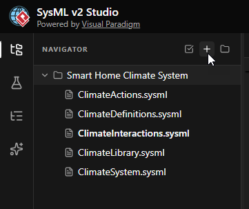
- Name the File
EnterClimateStates.sysmlas the filename and click Create.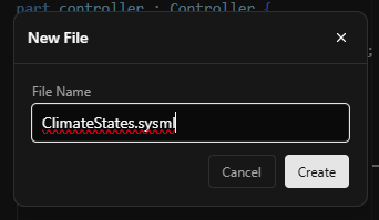
- Define the Package and Imports
Start by defining the package. We need to import three libraries: the standard units, our structural definitions, and crucially, our Action definitions from Step 5, so we can reference the regulation logic.package ClimateStates { private import ClimateLibrary::*; private import ClimateDefinitions::*; // Importing our actions package to see 'RegulateTemperature' private import ClimateActions::*; }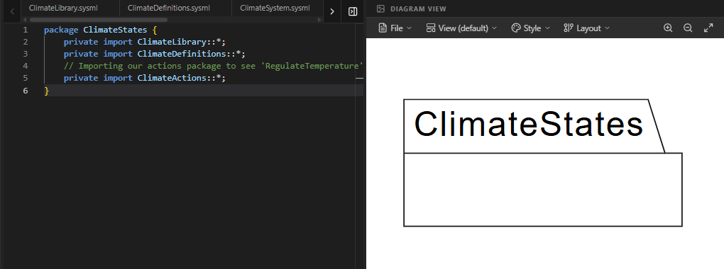
- Define Signal Triggers
Transitions often happen because of external events. We define simpleitem defelements to represent these signals. These act as the “messages” that trigger state changes.// We define items to represent the events that cause state changes. item def StartSignal; item def StopSignal;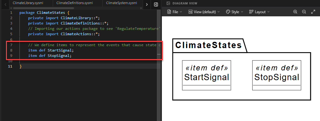
- Define the State Machine (
ClimateControlStates)
We define astate defto hold our logic. Inside, we first define the Initial State. In SysML v2, we use an emptyentryfollowed bythen state [Name]to indicate where the machine starts.state def ClimateControlStates { doc /* Defines the operational modes of the climate system. */ // A transition from the 'entry' point marks the starting state. entry; then state Idle; // State Definitions will go here... }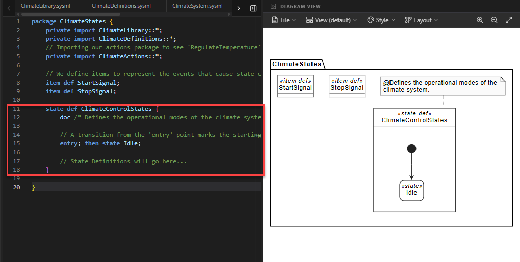
- Define the States (
IdleandHeating)
Inside the state definition, we define the two modes. Notice how theHeatingstate uses thedo actionkeyword to reference theRegulateTemperatureaction we created in Step 5.state Idle { doc /* System is waiting for a command. */ } state Heating { doc /* System is actively raising the temperature. */ // FIX: We must use the 'action' keyword to declare a local // usage typed by our blueprint. do action : RegulateTemperature; }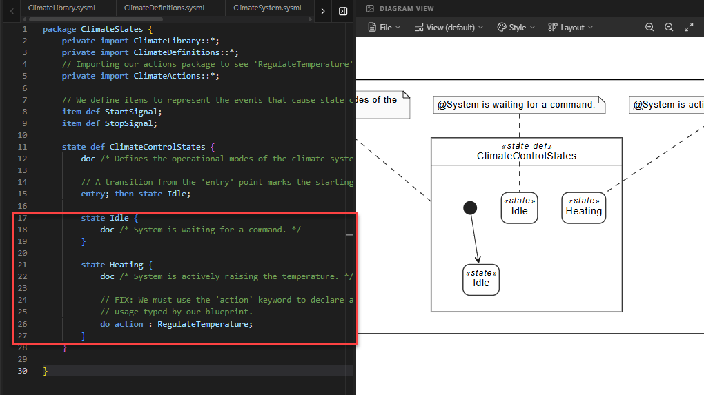
Code Explanation: The line
do action : RegulateTemperature;creates a local instance of the regulation logic and executes it continuously while the system is in the “Heating” state. - Define the Transitions
Now we define the rules for moving between states. We usetransitionblocks withfirst(source),accept(trigger), andthen(target).// Transition from Idle to Heating when a StartSignal is received transition idle_to_heating first Idle accept StartSignal then Heating; // Transition back to Idle when a StopSignal is received transition heating_to_idle first Heating accept StopSignal then Idle;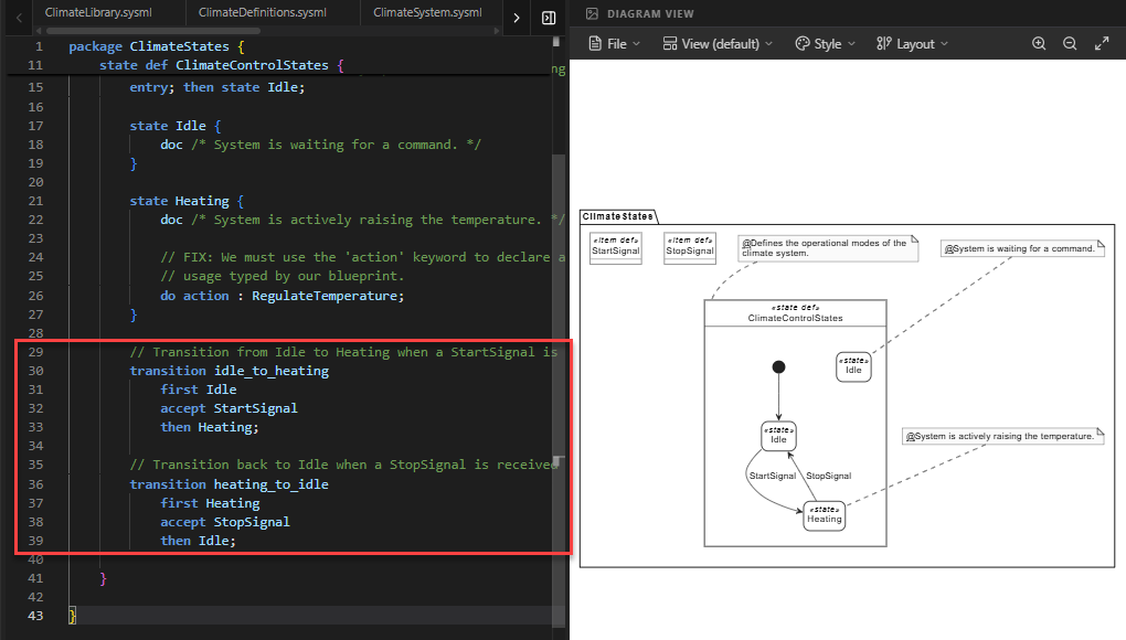
Code Explanation: This creates a loop. The system starts inIdle. When it accepts aStartSignal, it moves toHeating. When it accepts aStopSignal, it returns toIdle. - Assign Behavior to Hardware
Finally, we link this state machine to a physical part. We create a specialized controllerModeledControllerand useexhibit stateto declare that this part follows theClimateControlStateslogic.part def ModeledController :> Controller { // 'exhibit state' links the physical part to its modes. exhibit state controlModes : ClimateControlStates; }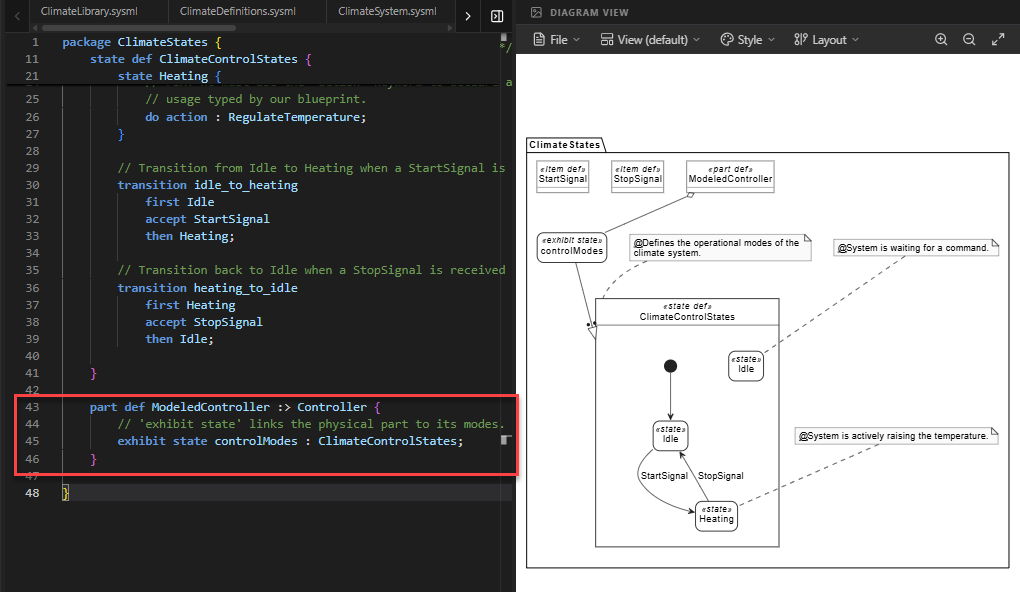
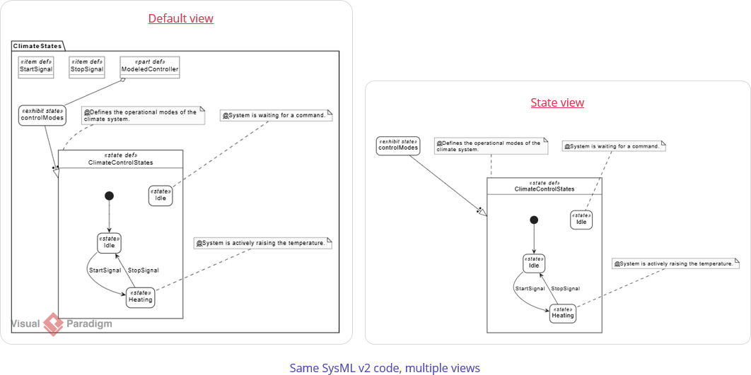
Focusing on the State Flow
You may notice that the default diagram view includes elements that are not part of the core state machine logic, such as the <<item def>> StartSignal and <<item def>> StopSignal definitions, as well as the package container. While these are important for the model’s structure, they can clutter the visualization when you want to analyze the behavioral flow.
To focus exclusively on the state machine, you can switch to the specialized State View.
How to Switch to State View:
- Click on the View dropdown menu located at the top of the Diagram Viewer panel.
- Select State from the list.
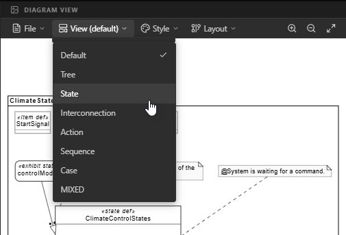
The diagram will refresh to display only the relevant behavioral elements: the Entry point, the States (Idle, Heating), and the Transitions between them. This provides a cleaner, more traditional State Machine diagram that is easier to read and verify.
Full Code for Step 7
package ClimateStates {
// 1. MODULAR IMPORTS
private import ClimateLibrary::*;
private import ClimateDefinitions::*;
// Importing our actions package to see 'RegulateTemperature'
private import ClimateActions::*;
// 2. SIGNAL DEFINITIONS (The Triggers)
    // We define items to represent the events that cause state changes.
    item def StartSignal;
    item def StopSignal;
// 3. STATE DEFINITION (The behavioral blueprint)
state def ClimateControlStates {
doc /* Defines the operational modes of the climate system. */
// 4. INITIAL STATE SETUP
// A transition from the 'entry' point marks the starting state.
entry; then state Idle;
// 5. THE STATES
state Idle {
doc /* System is waiting for a command. */
}
state Heating {
doc /* System is actively raising the temperature. */
// FIX: We must use the 'action' keyword to declare a local
// usage typed by our blueprint. Using 'do' directly with
// a name only works for referencing existing usages.
do action : RegulateTemperature;
}
// 6. THE TRANSITIONS (The Rules of Change)
        // Transition from Idle to Heating when a StartSignal is received
        transition idle_to_heating
            first Idle
            accept StartSignal
            then Heating;

        // Transition back to Idle when a StopSignal is received
        transition heating_to_idle
            first Heating
            accept StopSignal
            then Idle;
}
// 7. ASSIGNING BEHAVIOR TO HARDWARE
// We update our controller to show it follows these modes.
    part def ModeledController :> Controller {
        // 'exhibit state' links the physical part to its modes.
        exhibit state controlModes : ClimateControlStates;
    }
}Summary of SysML Elements Used
The table below summarizes the key SysML v2 elements introduced in this step, their purpose, and how they appear in the code.
| SysML Element | Purpose | Code Context |
|---|---|---|
state def |
Defines a blueprint for a state machine, containing states and transitions. | state def ClimateControlStates { ... } |
state [Name] |
Defines a specific mode of existence within the state machine. | state Idle { ... } and state Heating { ... }. |
do action : [Type] |
Declares a local action usage that executes continuously while in the state. | do action : RegulateTemperature; |
transition |
Defines the rule for moving from one state to another. | transition idle_to_heating ... |
accept |
Specifies the trigger (event/signal) that enables the transition. | accept StartSignal |
exhibit state |
Links a structural Part to a State Definition, indicating the part possesses this behavior. | exhibit state controlModes : ClimateControlStates; |
item def |
Defines a simple data type or signal used for triggers or communication. | item def StartSignal; |
Summary of What You Just Did
- Organized Behavior: You created a state machine to represent system modes.
- Integrated Views: You linked the Action View (Step 5) inside the State View (Step 6) using a
do actionusage. - Automated Transitions: You defined how external signals (
StartSignal) trigger system changes. - Bridged Structure and Logic: You used
exhibit stateto prove that your physical controller is capable of these behaviors.
In Step 8, we will create Requirement Traceability, using the satisfy keyword to prove that our assembly and behaviors meet the original rules we set in Step 2.
Ready to Model Your Own Systems?
Stop drawing static diagrams. Start building intelligent, verifiable models with SysML v2 Studio. Experience the power of the Digital Thread today.
