

Step 4: The Assembly Line – The Internal Block View (Part Usages and Connections)
In Step 3, you created a “catalog” of blueprints (Part Definitions). Now, it is time to build! In systems engineering, this is often called the Internal Block View. Here, we take those abstract blueprints and create specific occurrences (instances) of them, then “wire” them together to make a functional system.
This step introduces the most important distinction in SysML v2: Definition vs. Usage.
1. Definition vs. Usage: The Cookie and the Cutter
As we discussed briefly before, a Part Definition (part def) is the blueprint—it describes what kind of thing a sensor is. A Part Usage (part) is an actual occurrence of that thing in a specific context.
- Definition:
part def Sensor;(A generic blueprint for any sensor). - Usage:
part thermometer : Sensor;(A specific physical thermometer installed in our house).
A usage inherits all the features (attributes and ports) of its definition, but it allows you to specify exactly where it is located, what it is named, and how it connects to other parts.
2. System Decomposition: Nesting Usages
Systems are usually made of smaller subsystems. In SysML v2, we represent this by nesting part usages inside another part. When we place a thermometer inside home_01, the home becomes the composite owner of that thermometer. This hierarchical structure allows us to model complex systems from the top down.
3. Connections: The Digital Wiring
To make the parts interact, we use the connect keyword. A connection links two features—usually Ports—to allow data, power, or material to flow between them.
When connecting ports, we use Dot Notation (e.g., thermometer.tempOut) to navigate through the parts tree and find the specific connection points. This ensures that the wiring is explicit and traceable.
4. Binding: Asserting Equivalence
Sometimes, you don’t want to show a “flow” of data; you want to show that two attributes represent the same physical reality. For this, we use the bind keyword.
If we bind the home’s currentTemp attribute to the sensor’s reading attribute, we are asserting that they are mathematically equivalent in that context. If the sensor reads 20°C, the home’s temperature is 20°C. This is crucial for ensuring that requirements (which check currentTemp) are validated by the actual hardware (the sensor).
5. Modular Modeling: Cross-File Imports
In Step 3, we expanded a single file. In Step 4, we are creating a new file (ClimateSystem.sysml). This introduces a core architectural principle of SysML v2: Modularization.
Because our new file is separate from ClimateDefinitions.sysml, it does not automatically know what a Sensor or Controller is. We must explicitly import the previous package. This keeps our files clean and allows different teams to work on definitions and assembly simultaneously.
Hands-On: Creating ClimateSystem.sysml
In this step, we will create a new file to assemble our system. We will use Modular Imports to reference the blueprints we wrote in the previous steps.
- Create the New File
Navigate to your project folder Smart Home Climate System in the Navigator pane. Click on New File.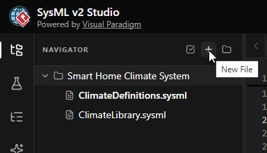
- Name the File
EnterClimateSystem.sysmlas the filename and click Create. This file will hold the specific instance of our smart home.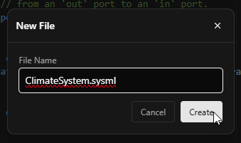
- Define the Package
Start by defining the new package namespace. This separates our specific system assembly from the general definitions.package ClimateSystem { }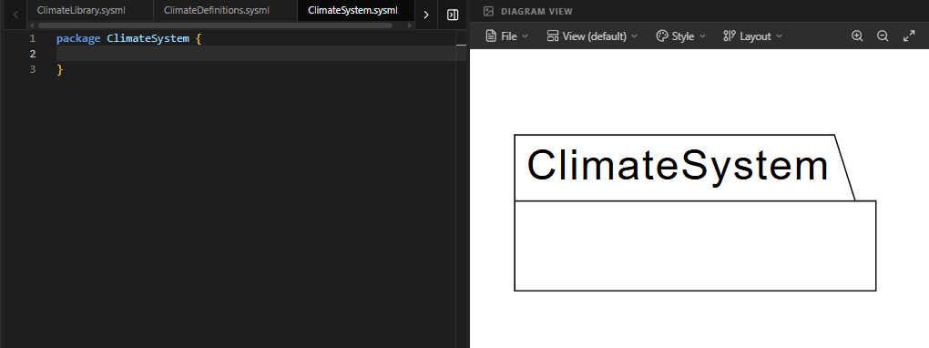
- Import the Blueprints
Since this is a new file, we must import the packages where our definitions live. We need both the standard library (for units) and our custom definitions (for Sensor/Controller).// Import standard units and types private import ClimateLibrary::*; // Import our custom blueprints (Sensor, Controller, SmartHome) private import ClimateDefinitions::*;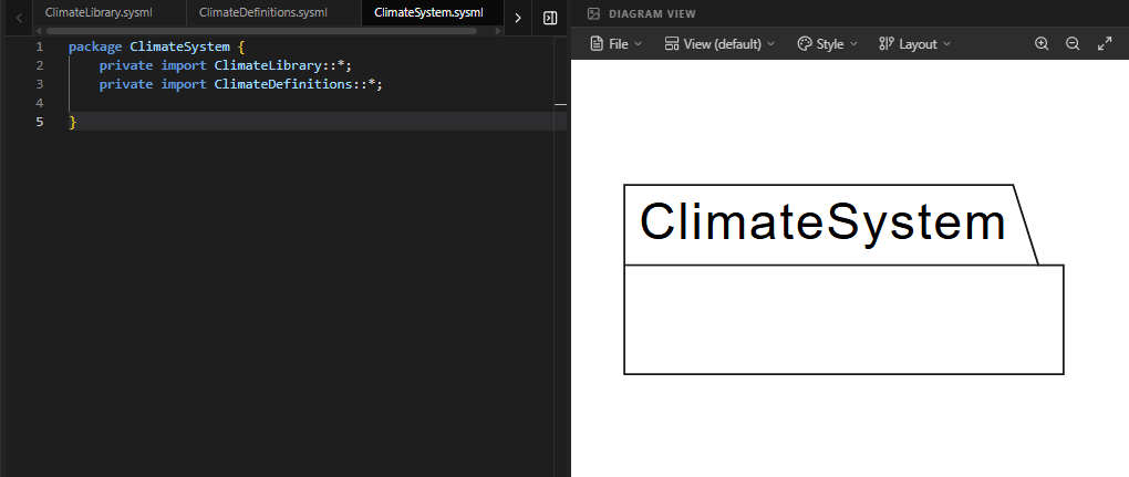
Code Explanation: The line
private import ClimateDefinitions::*;makes all public elements from Step 3 (likeSensorandController) available in this file without needing to type their full paths. - Create the System Instance (
home_01)
Now we create the actual system. We define apart(usage) namedhome_01that is typed by theSmartHomedefinition. Everything inside the curly braces ofhome_01represents the internal composition of this specific house.part home_01 : SmartHome { // Internal components go here }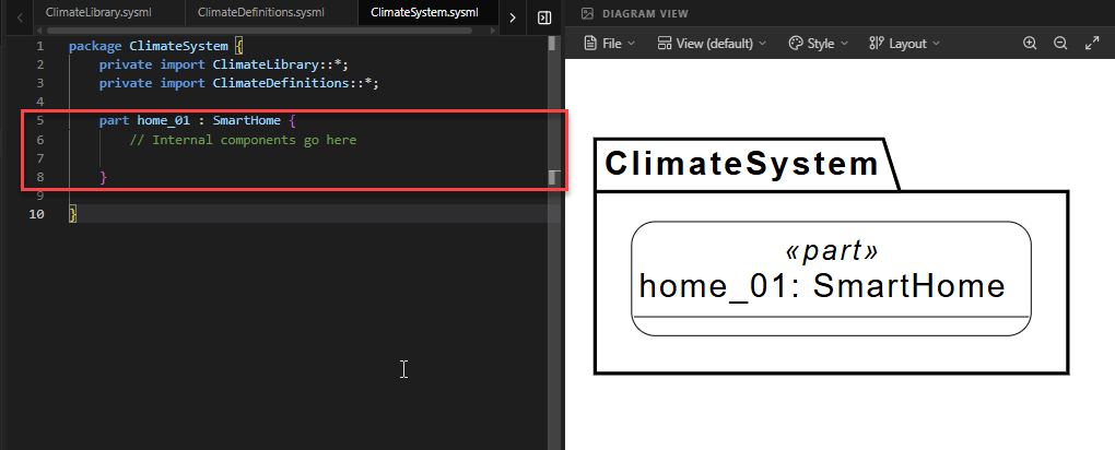
- Add Internal Part Usages
Insidehome_01, we instantiate the components. We create athermometer(typed bySensor) and amainController(typed byController). These are now real parts inside our virtual house.part thermometer : Sensor; part mainController : Controller;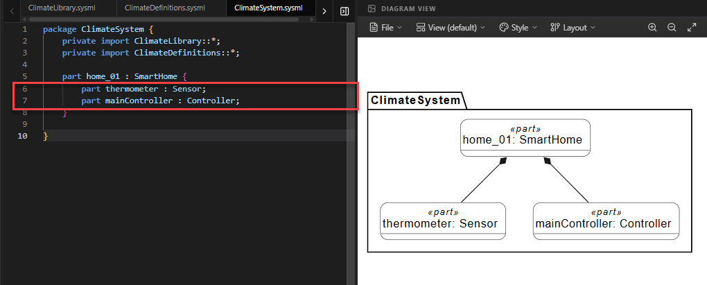
Code Explanation: By writing
part thermometer : Sensor, we are saying: “Create a part named ‘thermometer’ that follows the rules and structure of the ‘Sensor’ blueprint.” - Connect the Ports
Now we wire them up. We use theconnectkeyword to link the output port of the thermometer to the input port of the controller. Note the use of dot notation to access the ports inside the nested parts.connect thermometer.tempOut to mainController.tempIn;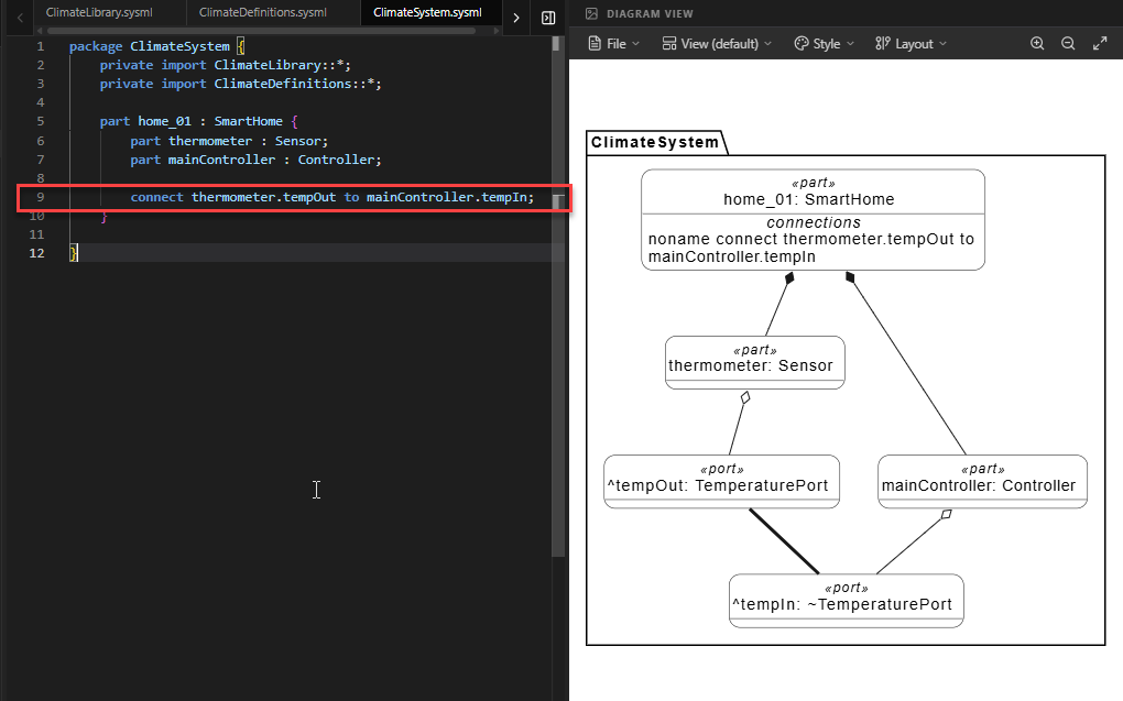
Code Explanation: This creates a communication channel. Data flowing out of
thermometerwill now flow intomainController. - Bind the AttributesFinally, we ensure the system’s state is accurate. We bind the
currentTempattribute of theSmartHome(which is the parent ofhome_01) to thereadingof the thermometer.bind currentTemp = thermometer.reading;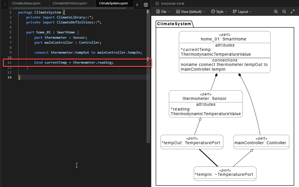
Code Explanation: This asserts that the
SmartHome‘s reported temperature is exactly equal to what thethermometersenses. This allows theTemperatureRequirementfrom Step 2 to be validated by the sensor data.
Full Code for Step 4
package ClimateSystem {
// 1. MODULAR IMPORT
// We bring in our shared library and our catalog of blueprints.
private import ClimateLibrary::*;
private import ClimateDefinitions::*;
// 2. THE MAIN SYSTEM ASSEMBLY (Internal Block View)
// We create a specific 'usage' of the SmartHome blueprint.
part home_01 : SmartHome {
// 3. INTERNAL PART USAGES (Decomposition)
// Here we 'instantiate' the blueprints inside our house.
part thermometer : Sensor;
part mainController : Controller;
// 4. THE CONNECTION (Wiring the parts)
// We link the sensor's output port to the controller's input port.
// SysML v2 uses 'connect .. to ..' for this purpose.
connect thermometer.tempOut to mainController.tempIn;
// 5. BINDING DATA
// We assert that the home's 'currentTemp' is exactly
// the same value as the thermometer's 'reading'.
bind currentTemp = thermometer.reading;
}
}Summary of SysML Elements Used
The table below summarizes the key SysML v2 elements introduced in this step, their purpose, and how they appear in the code.
| SysML Element | Purpose | Code Context |
|---|---|---|
part [name] : [Type] |
Defines a Usage (instance) of a Part Definition. It represents a concrete component in the system. | part home_01 : SmartHome creates a specific house instance. |
private import |
Brings elements from another package/file into the current scope, enabling modular design. | private import ClimateDefinitions::*; allows use of Sensor/Controller. |
connect ... to ... |
Establishes a flow or interaction path between two ports. | connect thermometer.tempOut to mainController.tempIn; |
bind ... = ... |
Asserts that two values or references are equivalent. Used for mapping internal data to external attributes. | bind currentTemp = thermometer.reading; |
Dot Notation (.) |
Used to access nested features (like ports or attributes) within a part usage. | thermometer.tempOut accesses the port inside the thermometer part. |
Conclusion
In this step, you have successfully assembled your first complete SysML v2 system model. You moved from abstract definitions to a concrete Internal Block View, creating a specific instance of a Smart Home (home_01) populated with a sensor and a controller. You learned how to connect these components to enable data flow and how to bind attributes to ensure system state consistency.
By using Modular Imports, you also demonstrated how SysML v2 supports large-scale engineering projects where definitions and implementations are managed in separate files. Your model is now structurally complete: it has requirements, blueprints, and a wired-up architecture. In the next steps, we will explore how to simulate this behavior or generate documentation from this rich model.
Ready to Model Your Own Systems?
Stop drawing static diagrams. Start building intelligent, verifiable models with SysML v2 Studio. Experience the power of the Digital Thread today.
