

SysML v2 8-View Guide – An Overview
Case Study: Smart Home Climate System
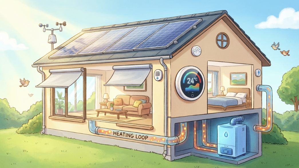
The Smart Home Climate System is a mission-critical automated system designed to maintain a habitable environment. At its core, the system must monitor the thermodynamic state of a house and intelligently manage heating resources to ensure the temperature remains within a safe and comfortable range.
The system is not just a collection of parts; it is an integrated solution that must handle physical quantities (temperature), hardware architecture (sensors and controllers), and automated logic (control algorithms).
Mapping the System to the 8 Modeling Steps
To build this system in SysML v2, we decompose the engineering process into eight progressive steps, each utilizing a specific “view” of the model.
1. The Digital Workspace (Foundations)
Before modeling hardware, we define the ClimateLibrary. This provides the “vocabulary” for the system, importing standard International System of Units (SI) like Kelvin [K] and quantities from the International System of Quantities (ISQ). This ensures that when the system measures “298.15 K,” the model knows exactly what that means mathematically.
2. Defining Success (Use Cases & Requirements)
The system exists to serve the HomeOwner (the Actor). We define the mission through a Use Case (“Manage Climate”) and a formal Requirement (“Temperature shall stay below 298.15 K”). Unlike traditional text requirements, this is a Requirement Definition containing a verifiable mathematical constraint.
3. Engineering the Blueprints (Block View)
We define the modular “cookie cutters” of our system: the Sensor and the Controller. These Part Definitions specify what the components are and how they talk to the world via Ports. We use Port Conjugation (~) to ensure the sensor’s “Output” fits perfectly into the controller’s “Input”.
4. Building the House (Internal Block View)
In this step, we move from blueprints to reality. We create a specific usage of our blueprints, named home_01. We “wire” the components together using Connections and use Binding Connectors to assert that the house’s temperature is exactly equal to the sensor’s reading, ensuring data consistency across the model.
5. The Control Algorithm (Action View)
A smart home needs “brains.” We model the RegulateTemperature action flow, which defines the chronological order of operations: Read Sensor → Compare Temps → Determine Command. We use Succession (first/then) to ensure the controller doesn’t try to process data before the sensor has provided it.
6. Interaction Modeling (Sequence View)
Systems are about communication. We model how parts interact over time by defining Lifelines and Messages. This Sequence View shows the precise time-ordering of events, such as a user sending a new temperature setpoint to the controller and receiving a confirmation.
7. Operational Modes (State View)
The system doesn’t always perform the same actions. It switches between discrete States—such as Idle and Heating. We define Transitions that fire only when specific signals (like a StartSignal) are received, allowing the system to exhibit complex, mode-dependent behavior.
8. Proving Compliance (Traceability)
This is where we “weave” the digital thread. We use the satisfy keyword to formally assert that our specific hardware assembly (home_01) meets the original TemperatureRequirement from Step 2. This creates a live link: if the design changes or the behavior fails a test, the requirement satisfaction will digitally “break”.
By following these 8 steps, you aren’t just learning SysML v2 syntax; you are learning how to build a Single Source of Truth. Whether you are looking at the high-level requirement or the low-level sensor port, every element is part of a single, interconnected digital record of the Smart Home Climate System.
About this Tutorial
This tutorial is designed to be beginner-friendly and progressive. We avoid overly complex technicalities to focus on the essential constructs you need for daily engineering tasks.
Your learning journey is divided into nine modular steps:
-
- Foundations & Organization: Learn to use Packages and Libraries to set up a professional workspace.
- The Mission: Define Use Cases and verifiable Requirements with formal mathematical rules.
- Blueprints (Block View): Create Part Definitions (blueprints) for sensors and controllers using ports and attributes.
- System Assembly (Internal Block View): Use Part Usages and Connections to “wire” your system together.
- Behavioral Flow (Action View): Model the chronological logic of how data flows through a process.
- Interaction Modeling (Sequence View): Define Lifelines and Messages to show how components talk to each other over time.
- Discrete Modes (State View): Define how the system switches between modes like “Idle” and “Heating”.
- The Digital Thread (Traceability): Formally Satisfy requirements to prove your design meets the mission needs.
How to Use This Tutorial
Each step provides the full code for that specific module. We utilize a modular approach, meaning you will learn how to use the import keyword to reference your work across different files, just as you would in a real-world engineering project.
Are you ready to move from drawing boxes to engineering data? Let’s begin with Step 1.
Ready to Model Your Own Systems?
Stop drawing static diagrams. Start building intelligent, verifiable models with SysML v2 Studio. Experience the power of the Digital Thread today.
