

Introduction
Systems modeling has evolved significantly over the past decade, and SysML v2 represents a paradigm shift toward precision, interoperability, and text-first authoring. Built on a rigorous KerML (Kernel Modeling Language) foundation, SysML v2 moves away from heavy graphical abstractions and embraces a structured, human-readable, and machine-parsable syntax. For beginners, this transition can feel unfamiliar, but it ultimately streamlines collaboration, version control, and automated validation.
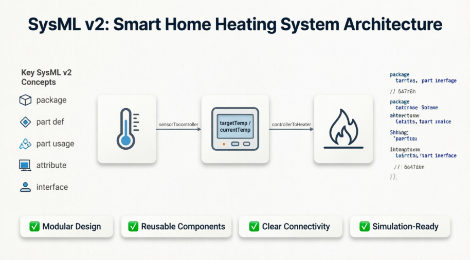
This guide walks you through the structural modeling of a real-world Smart Home Heating System using SysML v2’s textual notation. By the end, you will understand how to define components, instantiate them, establish connections, and organize your model effectively using packages. Whether you are a systems engineering student, a software developer, or a hardware architect, the concepts covered here will serve as a solid foundation for building scalable, maintainable system models.
Problem Context
A homeowner requires an automated indoor temperature management system. The architecture comprises three core components:
-
A Temperature Sensor that continuously monitors ambient conditions.
-
A Smart Thermostat that receives sensor data, compares it against a user-defined threshold, and issues control commands.
-
A Heating Unit that activates or deactivates based on thermostat instructions.
All components communicate securely within a Home Network domain. The goal is to capture this architecture structurally in SysML v2, ensuring clear boundaries, explicit relationships, and reusable definitions.
SysML v2 Package Diagram (by VP SysML v2 Studio)
In SysML v2, textual modeling is the primary authoring method. Below is the complete KerML-based package definition for the Smart Heating System:
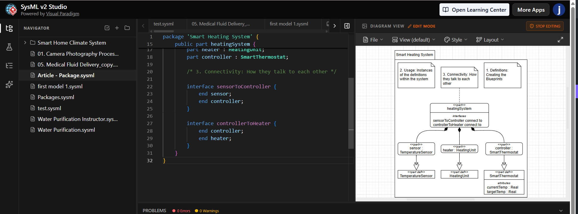
SysML V2 – Text Notation
package 'Smart Heating System' {

    /* 1. Definitions: Creating the Blueprints */

    public part def TemperatureSensor;
    public part def HeatingUnit;

    public part def SmartThermostat {
        attribute targetTemp: ScalarValues::Real;
        attribute currentTemp: ScalarValues::Real;
    }

    /* 2. Usage: Instances of the definitions within the system */

    public part heatingSystem {
        part sensor : TemperatureSensor;
        part heater : HeatingUnit;
        part controller : SmartThermostat;

        /* 3. Connectivity: How they talk to each other */

        interface sensorToController {
            end sensor;
            end controller;
        }

        interface controllerToHeater {
            end controller;
            end heater;
        }
    }
}
Deep Dive: Core Elements & Key Concepts Highlights
The textual syntax above may look concise, but each keyword carries specific semantic weight. Below is a comprehensive breakdown tailored for beginners:
🔹 package
A namespace container that groups related modeling elements. It prevents naming collisions, establishes scope, and enables modular organization. Packages can be nested, imported, and reused across projects.
🔹 part def (Part Definition)
Represents a type blueprint. It answers the question: What kind of component is this? A definition does not occupy memory or represent a physical object; it establishes shared characteristics, constraints, and potential behaviors that multiple instances can inherit.
🔹 part (Part Usage)
Represents a concrete instance within a specific context. When you write part heater : HeatingUnit, you are declaring that the current system contains one physical or logical heater conforming to the HeatingUnit blueprint. Usage allows you to bind definitions to a specific architectural scope.
🔹 attribute
Defines data properties held by a part. In SysML v2, attributes are strongly typed. ScalarValues::Real indicates a floating-point numeric value. Attributes are essential for parametric analysis, simulation, and runtime state tracking.
🔹 interface
Replaces the legacy SysML v1 concept of ports and connectors. An interface explicitly declares a communication channel or relationship between two part usages. The end keyword binds the interface to specific parts, ensuring unambiguous data flow and command routing.
🔹 public
Controls visibility. Public elements are accessible to external packages, enabling cross-project reuse and library distribution. Omitting visibility modifiers typically defaults to package-private or local scope, depending on the modeling environment.
When & Why to Use the package Element
The package keyword is the backbone of architectural organization in SysML v2. Understanding when and why to apply it will dramatically improve model maintainability.
📦 Primary Purposes
-
Namespace Management: Prevents duplicate naming across large projects. Two engineers can define
TemperatureSensorin separate packages without conflict. -
Modularity & Reusability: Encapsulates logically grouped elements (e.g., hardware, software, network topology, requirements). These packages can be exported as libraries and imported into other system models.
-
Access Control & Security: Visibility modifiers (
public,private,protected) let you expose only what other teams need while hiding implementation details. -
Tooling & Automation: Modern SysML v2 tools rely on package boundaries for code generation, validation, version control diffing, and simulation scoping.
🛠 When to Create a New Package
-
Domain Separation: When modeling crosses distinct engineering disciplines (e.g.,
package Electrical,package Thermal,package ControlLogic). -
Library Development: When creating reusable component catalogs (e.g.,
package IoT Device Library). -
Project Scaling: Once a single file exceeds ~200 lines or contains more than 15-20 interconnected elements, split into logical packages.
-
Team Collaboration: When multiple contributors work on different subsystems simultaneously. Assign each team a dedicated package to minimize merge conflicts.
Practical Mapping: From Text to Real-World System
Understanding how the model translates to physical behavior bridges the gap between abstract syntax and engineering reality:
-
Blueprint Creation:
TemperatureSensor,HeatingUnit, andSmartThermostatare defined first. This mirrors procurement or design specification phases where component types are selected. -
System Instantiation:
heatingSystemacts as the top-level assembly. Declaringsensor,heater, andcontrollermirrors the physical mounting and wiring process. -
Data Flow Establishment:
-
sensorToControllerrepresents the wired or wireless telemetry link carrying real-time temperature readings. -
controllerToHeaterrepresents the control signal (e.g., PWM, relay trigger, or MQTT command) that activates heating elements.
-
-
Attribute Tracking:
targetTempandcurrentTempon the thermostat enable runtime state evaluation. In a full SysML v2 model, these would later feed intoConstraintBlockdefinitions for simulation and threshold logic.
This structured approach ensures that every physical connection, data exchange, and component type is explicitly declared, validated, and ready for downstream analysis.
Conclusion
SysML v2’s text-first, KerML-based syntax removes the ambiguity of traditional diagram-centric modeling while preserving rigorous systems engineering principles. By mastering package organization, understanding the distinction between part def and part, and leveraging interface for clean connectivity, beginners can rapidly construct scalable, simulation-ready architectures. The Smart Home Heating System example demonstrates how a few dozen lines of precise notation can capture complex hardware-software interactions, data attributes, and secure communication boundaries.
As you progress, explore SysML v2’s behavioral elements (action, state, transition), parametric modeling for physics-based simulation, and integration with digital thread platforms. Systems modeling is no longer just about drawing boxes and lines; it is about creating executable, verifiable, and reusable digital representations of reality. Start small, validate often, and let the structure guide your design.
References
- SysML v2 KerML Specification: Official Kernel Modeling Language specification detailing the foundational syntax, semantics, and modeling constructs used in SysML v2.
- SysML v2 Structural Modeling Guide: Comprehensive documentation covering package organization, part definitions, interfaces, and structural composition best practices.